Machine Vision
Machine vision uses cameras, controlled lighting, and image analysis to inspect, measure, identify, and guide parts on production lines in real time.
Machine vision (MV) is the use of cameras, optics, lighting, and image analysis in industrial automation to inspect products, measure parts, read codes, and guide machines, with every result driving an action such as rejecting a part, sorting it, or steering a robot. It is computer vision engineered into a control loop: a vision system on a packaging line has to finish each decision within the line's cycle time, tens of milliseconds per part on a fast bottling line, and report it to a programmable logic controller (PLC) through digital I/O or an industrial network. Its tasks are usually grouped into four families: guidance (locating parts for robots), inspection (finding defects and missing features), gauging (measuring dimensions), and identification (reading barcodes, data matrix codes, and printed text with optical character recognition).
Machine Vision vs. Computer Vision and Image Processing#
Machine vision applies image processing, which transforms images by filtering noise or sharpening edges, and computer vision, which extracts meaning from images in any setting, to industrial machines. It is defined by its hardware and its integration: controlled lighting and optics, cameras triggered by sensors on the line, deterministic timing, and outputs wired to actuators. The difference between the three fields is mostly scope, and modern machine vision systems run the same deep learning models as other computer vision applications.
Components of a Machine Vision System#
- Lighting: Illumination decides what the camera can see. Backlights turn parts into silhouettes for precise edge measurement, diffuse dome lights suppress glare on shiny surfaces, low-angle dark-field lights make scratches and embossed characters stand out, and projected laser lines reveal 3D height profiles.
- Optics: Telecentric lenses keep magnification constant as the distance to the part varies, so gauging results do not depend on where the part sits.
- Cameras: Area-scan cameras capture discrete parts in one exposure, line-scan cameras build images of continuous materials such as steel, paper, and textiles one row at a time, and 3D sensors use laser triangulation, stereo vision, or time of flight. Interface standards such as GigE Vision, USB3 Vision, and GenICam let software control cameras from different vendors.
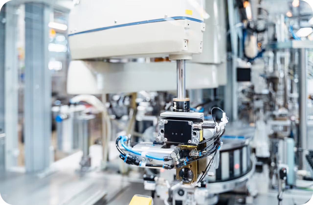
- Processing and I/O: A photoelectric sensor or encoder triggers each capture, a smart camera or industrial PC runs the analysis, and the result goes to the PLC, increasingly on edge hardware with a GPU or NPU.
Rule-Based Tools and Deep Learning#
Classic machine vision software chains deterministic tools: thresholding, blob analysis, edge detection, pattern matching, and calipers that measure the distance between edges. This example runs blob analysis on a photo of coins, counting the parts and gauging their size:
import numpy as np
from scipy import ndimage as ndi
from skimage import data, filters, measure, segmentation

# Grayscale photo of 24 Greek coins on a gray background, bundled with scikit-image
image = data.coins()

# Seed the background (dark) and the parts (bright), then grow both along edge strength
markers = np.zeros_like(image)
markers[image < 30] = 1
markers[image > 150] = 2
mask = ndi.binary_fill_holes(segmentation.watershed(filters.sobel(image), markers) == 2)

# Blob analysis: label each part, ignore specks, and gauge each diameter in pixels
parts = [r for r in measure.regionprops(measure.label(mask)) if r.area > 300]
diameters = [part.equivalent_diameter_area for part in parts]
print(f"{len(parts)} parts, diameters {min(diameters):.0f}-{max(diameters):.0f} px")
It prints 24 parts, diameters 37-63 px: every coin is found and measured, and a production system would compare each diameter with a tolerance and send the result to the PLC. The background in this photo brightens toward the upper left and shares gray levels with the coins, so a single global Otsu threshold breaks the image into 96 blobs, a problem that controlled lighting prevents on a production line.
Rule-based tools are fast, explainable, and exact for parts with fixed geometry, but they struggle with natural variation such as wood grain, food, or cosmetic defects that take many shapes. Object detection, instance segmentation, and anomaly detection models learn those cases from examples. A YOLO26 segmentation model trained on defect images outlines scratches and cracks pixel by pixel, and Ultralytics export mode converts it to TensorRT or OpenVINO so that real-time inference fits within the line's cycle time on an industrial PC or NVIDIA Jetson.
Real-World Applications#
- Automated optical inspection: Electronics lines inspect printed circuit boards for missing, shifted, or reversed components and faulty solder joints, often with 3D solder paste inspection before components are placed.
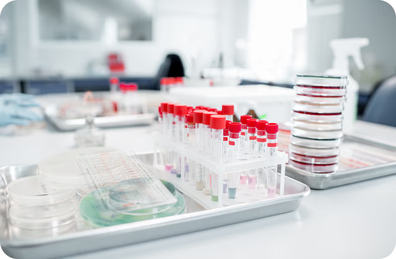
- Pharmaceutical and packaging inspection: Systems verify fill levels, caps, and labels, and OCR reads the printed lot code and expiry date on every package.
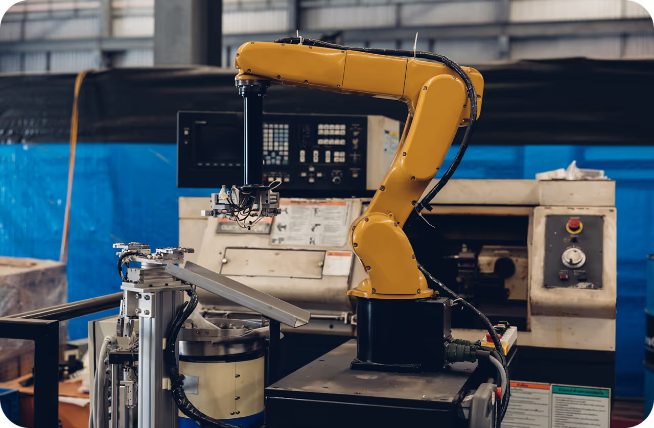
- Vision-guided robotics: Robots locate randomly piled parts for bin picking, using 3D sensors and pose estimation to choose a grasp.
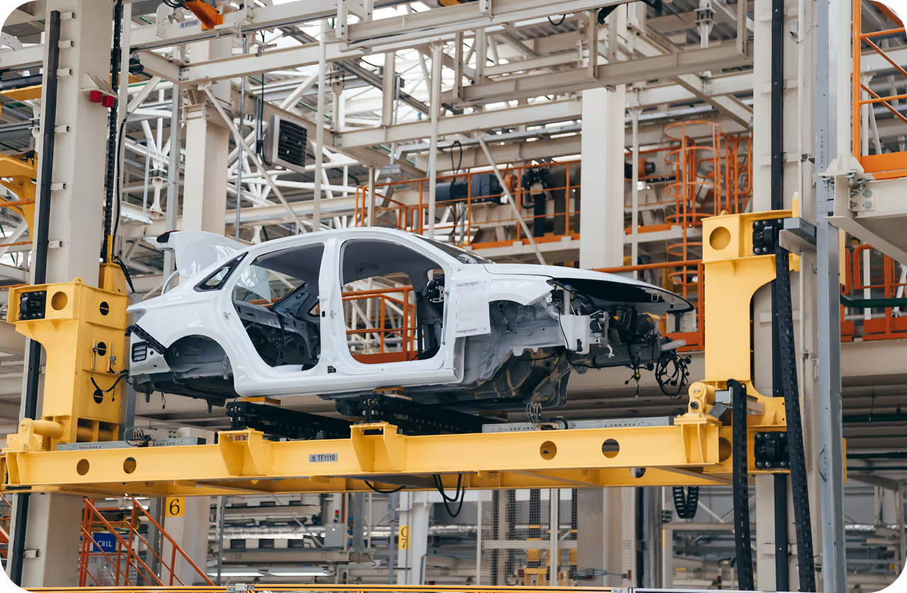
- Automotive manufacturing: 3D sensors measure the gap and flush between body panels, and cameras check paint finish and weld seams before vehicles leave the line.