Assembly Verification and Error-Proofing with Computer Vision
How computer vision verifies assembly completeness, correctness and sequence: imaging station design, model task choice, PLC integration and validation.
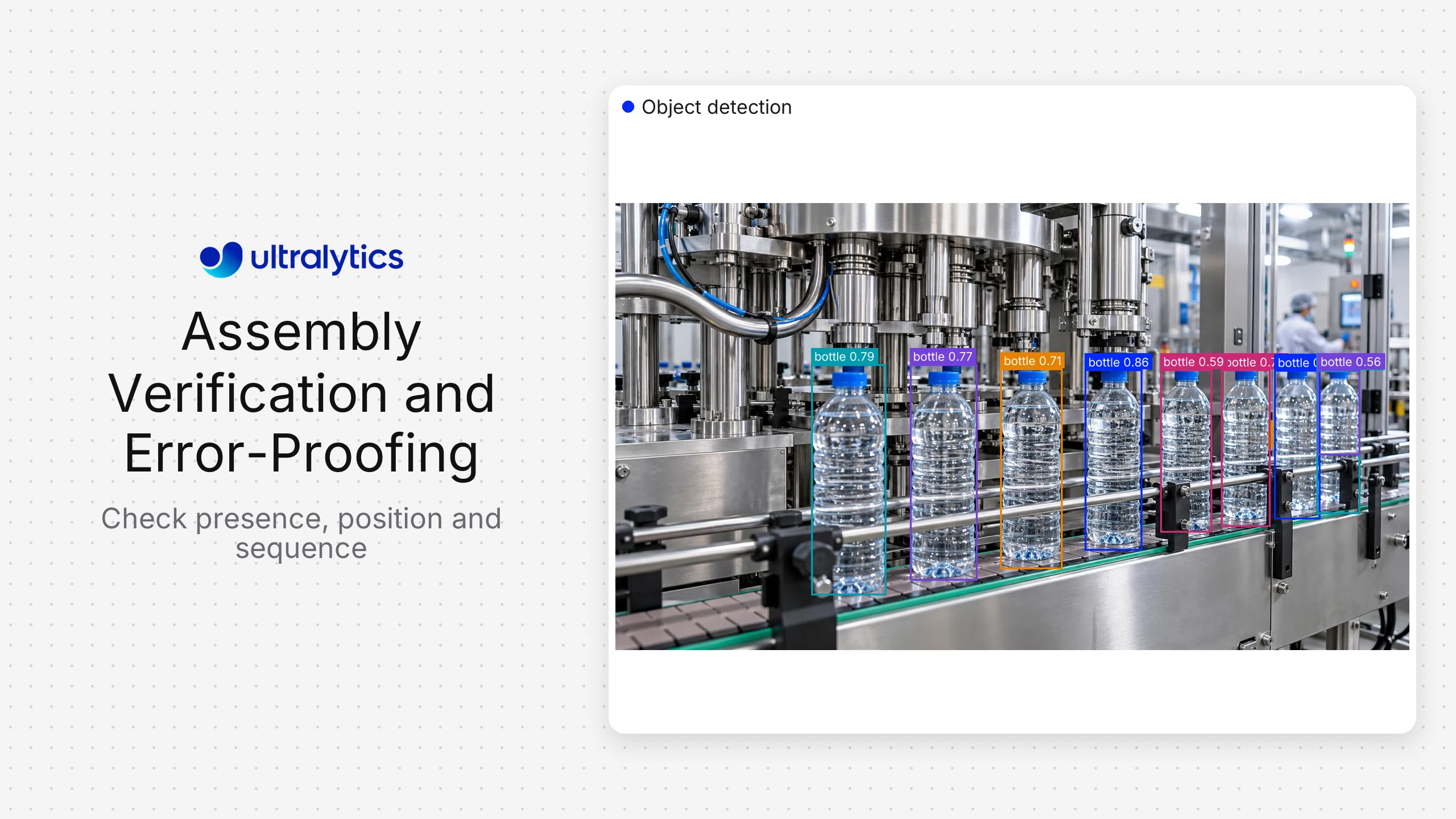
Computer vision can error-proof assembly by checking whether the right visible component is present, correctly positioned, correctly oriented, and installed in the expected sequence before the process advances. The model supplies visual observations; a state machine or manufacturing application applies product-specific rules and sends a pass, review, or stop decision to the operator or control system.
This is different from general defect detection. Defect inspection asks whether a surface or part is damaged. Assembly verification asks whether the observed build state matches the work instruction or bill of process.
What vision can verify on an assembly line#
| Verification task | Visual question | Common vision task | Important limitation |
|---|---|---|---|
| Part presence | Is the required component visible? | Object detection or classification | Occlusion can hide an installed part |
| Position | Is the component inside the allowed region? | Detection or segmentation | Image coordinates may require calibration |
| Orientation | Is the part facing the correct direction? | Keypoints, oriented boxes, or classification | Symmetric parts need distinctive visual features |
| Count | Is the required quantity present? | Detection plus tracking/counting | Overlap can cause missed or duplicate counts |
| Sequence | Did states occur in the approved order? | Detection/tracking plus a state machine | The model alone does not encode the process sequence |
| Fastener presence | Are visible fasteners in expected locations? | Detection or segmentation | Vision cannot prove hidden torque |
| Connector state | Is a visible latch or connector seated? | Detection, segmentation, or classification | Camera angle and resolution must expose the state |
| Label or code match | Does the visible identifier match the work order? | Detection plus OCR/barcode logic | Text quality and integration determine reliability |
Start by separating observable evidence from inferred process facts. A camera may verify that a bolt head is present but not that the bolt has the required torque. Pair vision with tool-controller or sensor data when the requirement is not visually observable.
A reference architecture#
An assembly-verification system usually contains six layers:
- Trigger: A PLC signal, sensor, robot state, or operator action identifies the verification moment.
- Capture: One or more cameras acquire a controlled image or short sequence.
- Inference: A computer vision model detects parts, regions, keypoints, or assembly states.
- Decision logic: Product rules compare observations with the expected variant and process step.
- Action: The system displays guidance, requests review, records a pass, or blocks progression through an approved control path.
- Traceability: The application records the work order, model and rule version, result, and evidence permitted by the retention policy.
Keep inference and decision logic separate. The same model may recognize a component across products, while rules specify which components are required for a particular work order.
Choose the right vision task#
Use classification when the entire view is tightly controlled and the output is a small number of states such as assembled, incomplete, or wrong orientation. It can be efficient, but it gives limited localization when troubleshooting.
Use object detection when the application needs to locate and count several visible components. Ultralytics YOLO models can detect multiple part classes in one image and return locations for downstream rules.
Use instance segmentation when component boundaries, overlap, or coverage matter. A mask can support checks that a seal, adhesive region, or flexible component occupies the expected area.
Use pose estimation or oriented bounding boxes when keypoints or rotation carry the important signal. Validate that the selected representation is stable for the exact geometry and viewpoint.
Use tracking when sequence or continuity matters. A tracker can associate observations across frames, while a state machine determines whether approved steps occurred in order.
Design the imaging station before training#
Model quality cannot compensate for evidence the camera never captures. For each check, document the smallest feature that must be resolved, allowed part motion, cycle time, working distance, depth variation, reflections, occlusion, and vibration.
Control lighting where practical. Diffuse light can reduce glare on reflective surfaces; backlighting can make silhouettes and gaps clearer; strobed lighting can reduce motion blur. The appropriate design depends on material and geometry, so test with real parts and contamination conditions.
Use multiple views when a single camera cannot observe every required feature. Do not add cameras automatically: every view increases calibration, synchronization, compute, maintenance, and data-management work. Each camera should close a documented evidence gap.
Lock or monitor camera settings after validation. A changed focus, exposure, crop, or mount can invalidate the data distribution even if the endpoint remains healthy.
Build the assembly dataset#
Capture all relevant product variants, stations, shifts, backgrounds, tooling states, and normal operator interactions. Include difficult but valid states as well as errors. If every “good” image comes from one day and every “bad” image from another, the model may learn lighting or fixture differences instead of assembly state.
Write labeling rules for partially visible parts, ambiguous states, reflections, duplicate components, and work in progress. Split validation data by production run, time, station, or site rather than randomly distributing near-identical video frames.
Ultralytics Platform supports dataset organization, annotation, model training, and model management in a connected workflow. Its data collection and annotation guide can help teams formalize capture and labeling decisions.
Add process logic and integrations#
The application needs the expected build configuration for the current unit. Retrieve it from an approved source such as the work order, recipe, or manufacturing system, then map it to versioned visual rules.
A rule might require:
- One housing inside a fixture region.
- Two clips in approved locations.
- A connector keypoint within tolerance of its target.
- State A before state B, with no unapproved state between them.
- A human review when any required observation is below its decision threshold.
Use a stable event contract between vision and controls. Include result, reason, timestamp, station, model version, rule version, and the relevant observations. Avoid sending raw model output directly to safety-critical or motion-control logic without a validated application layer and appropriate safeguards.
Operator experience is part of accuracy#
A red or green light rarely gives enough information. When a unit fails, show which requirement failed and where the relevant component was expected. Provide a controlled rescan or review path so reflections, hands, or temporary occlusion do not create unnecessary rework.
Collect operator corrections as structured feedback. Distinguish a model error from a rule error, wrong work-order mapping, camera issue, or genuine assembly problem. That classification tells the team what to fix.
Validate the complete station#
Measure by assembly requirement and product variant. Useful operational measures include missed assembly errors, false stops, review rate, cycle-time effect, unavailable checks, and successful recovery after a camera or network interruption.
Challenge the station with:
- Approved and unapproved variants.
- Partial assemblies and out-of-sequence steps.
- Occlusion by hands and tools.
- Lighting drift, reflective parts, blur, and contamination.
- Camera movement and focus changes.
- Duplicate, missing, rotated, or misplaced components.
- Lost triggers, duplicate triggers, and late results.
Run the incumbent and candidate model on a fixed regression set before release. Where risk warrants it, shadow the new decision logic without controlling the process until results are reviewed.
Ultralytics for assembly verification#
Computer vision in manufacturing can use detection, segmentation, pose, and tracking to represent visible assembly states. Ultralytics Platform connects annotation, training, and deployment, while exported Ultralytics YOLO models can run in cloud, on-premises, or edge architectures selected for the station.
Chef Robotics provides a practical example of Ultralytics YOLO supporting precise food assembly. The transferable lesson is not that every assembly line has the same imaging problem, but that a trained perception model can become one component in a larger robotic or production workflow.
What Ultralytics does not provide. This is a perception layer, not an inspection station. The camera, lens, lighting, enclosure, trigger, edge computer, PLC connection, operator HMI and station validation remain yours or your integrator's, and they are the larger part of the work. Where a plant wants a supported turnkey station with a field engineer attached, an established machine-vision vendor such as Cognex or Keyence is the sounder choice, and Ultralytics Platform launched in March 2026 against decades of their deployment history.
Rollout checklist#
- Define every check as visible evidence and an operational action.
- Record non-visual requirements that need another sensor or system.
- Validate camera, lens, lighting, trigger, and mounting with real parts.
- Version product rules separately from the model.
- Test every product variant and work-in-progress state.
- Provide review, rescan, bypass, and incident procedures.
- Monitor input quality, service health, reviewed model errors, and production outcomes.
- Revalidate after camera, lighting, fixture, product, or process changes.
Frequently asked questions
It is visual error-proofing that checks observable assembly conditions and supports an action before an error moves downstream. The vision result is usually combined with product rules and the manufacturing workflow.
Yes, when relevant states are visible over time. Detection or tracking supplies observations, and a state machine compares their order with the approved process. The system must handle missed frames, repeated steps, and uncertain observations.
Usually not from appearance alone. Vision may verify visible fastener presence, location, or marking, while torque should come from a validated tool controller or sensor.
Assembly verification checks configuration, presence, orientation, and process state. Defect detection looks for damage or quality anomalies. A station may perform both, but the data, logic, and acceptance criteria should remain explicit.
It depends on the evidence: classification for controlled whole-image states, detection for part presence and count, segmentation for boundaries and overlap, pose or oriented boxes for geometry, and tracking for sequence. Test the simplest task that exposes the required evidence reliably.