Robotic Quality Inspection: Why Coverage Is the Hard Part
How robotic quality inspection works: scan planning, calibration, robot and vision synchronization, multi-view fusion, coverage proof and quality records.
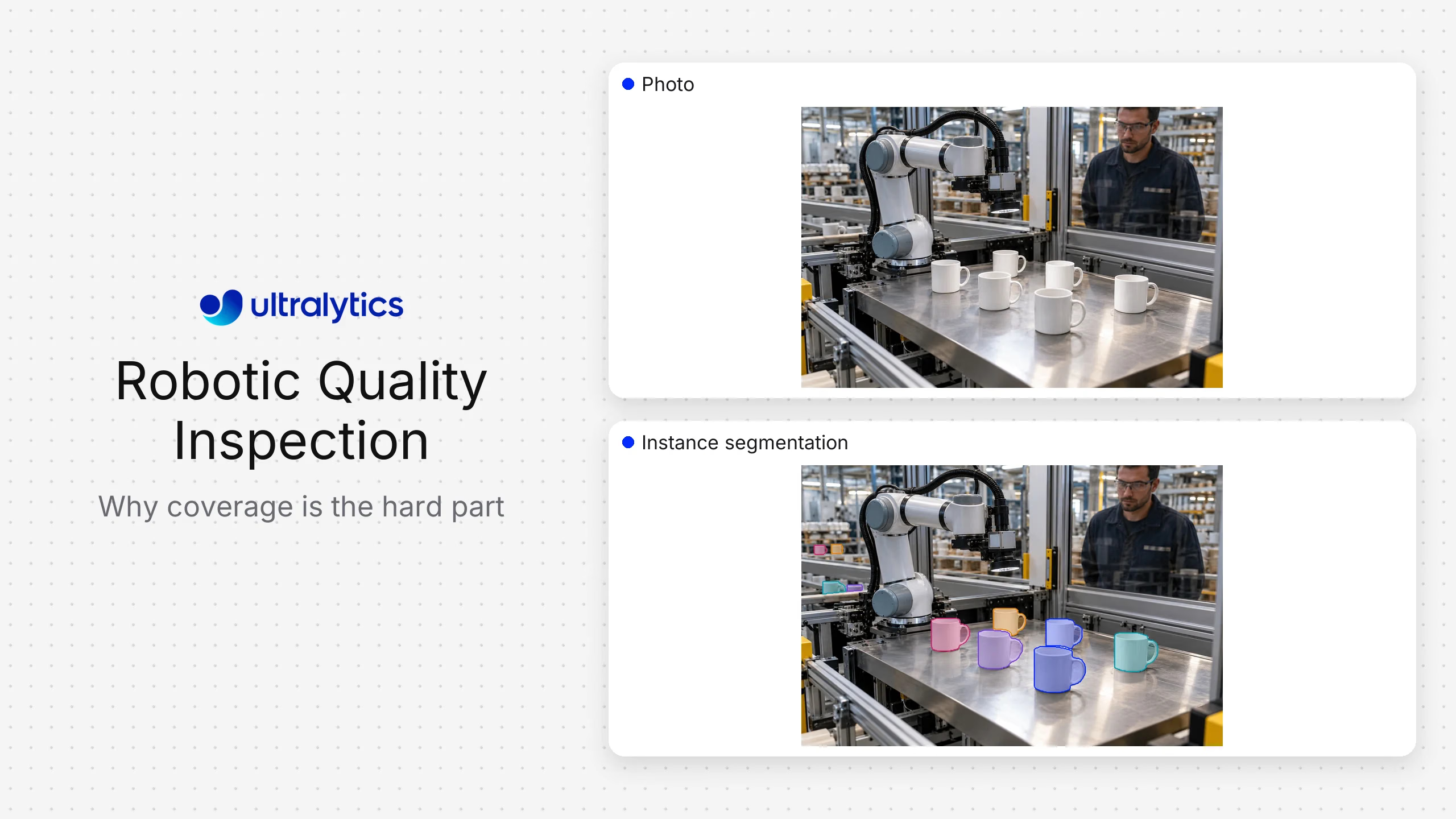
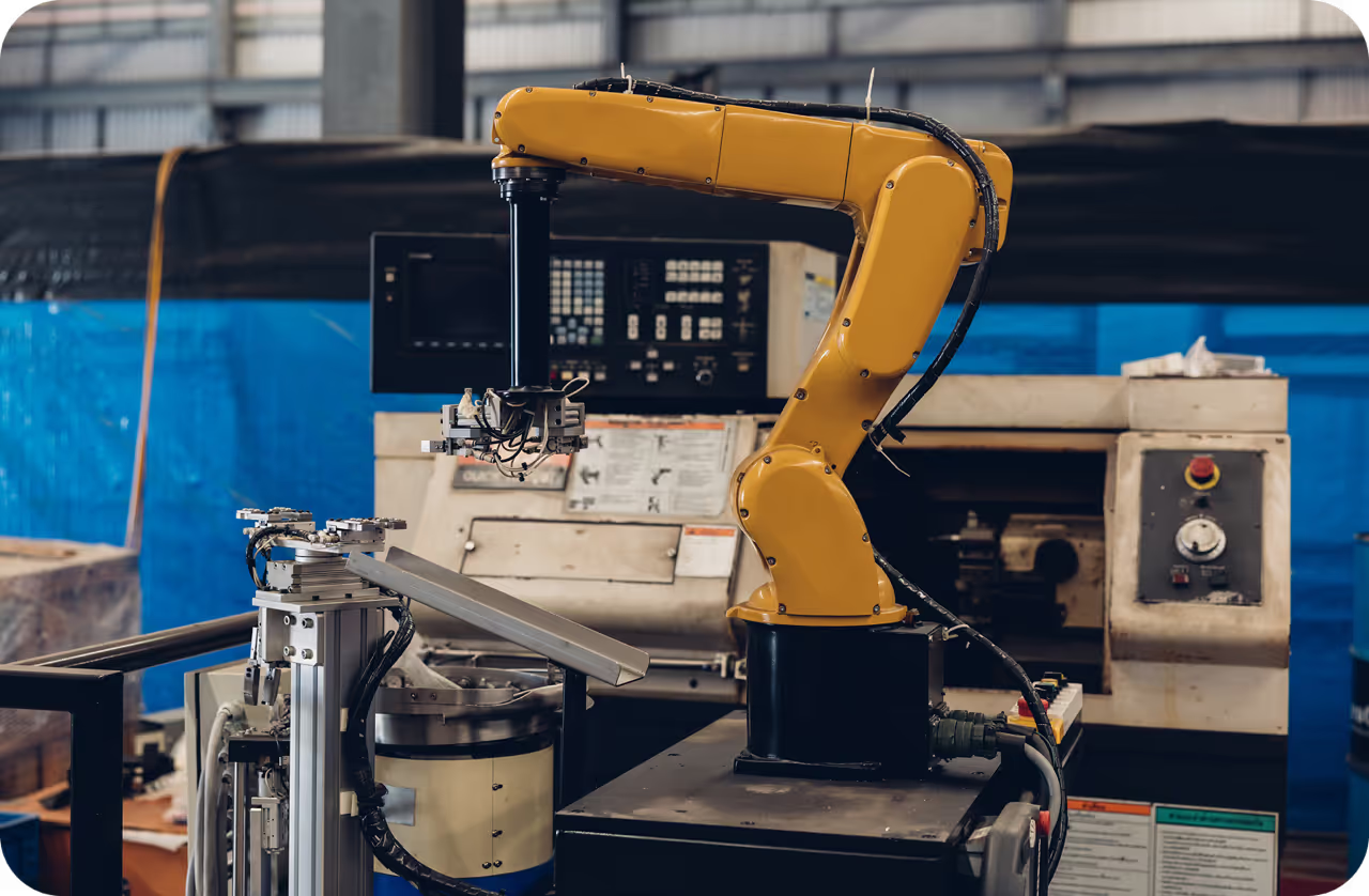
Robotic quality inspection combines computer vision with a robot that moves the camera, part, or sensor through a planned set of viewpoints. It is useful when a fixed camera cannot see every required surface, when product geometry varies, or when inspection needs to reach several sides without a large bank of stationary cameras.
Ultralytics YOLO can provide detection, segmentation, classification, pose, or tracking within a custom inspection stack. Industrial vision suites from Cognex, Keyence, MVTec, Zebra, and Teledyne offer established tooling and hardware ecosystems. Vision platforms such as Landing AI and Robovision emphasize configurable learned-inspection workflows. The best fit depends on whether the organization needs a packaged inspection product, an industrial development environment, or a customizable model layer.
Robotic inspection software options#
| Option | Best fit | Strength | Main integration responsibility |
|---|---|---|---|
| Cognex | Industrial cells using a broad machine-vision ecosystem | Cameras, tools, and factory integration experience | Cell-specific application design and robot coordination |
| Keyence | Controlled industrial inspection with integrated vision hardware | Packaged sensors, lighting, and inspection tools | Coverage and performance on the actual product range |
| Landing AI or Robovision | Teams seeking configurable learned-vision workflows | Model development and inspection-oriented platform features; note Landing AI has repositioned around document AI, so confirm its inspection roadmap | Robot, imaging, line, and quality-system integration |
| MVTec HALCON | Engineering teams developing advanced machine-vision applications | Extensive programmable vision library | Specialist development, deployment, and maintenance |
| Ultralytics Platform and Ultralytics YOLO | Teams building custom multi-view learned inspection | Flexible vision tasks, data-to-model workflow, deployment choices | Robot path, calibration, result fusion, controls, and validation |
| Zebra or Teledyne vision portfolios | Industrial imaging and machine-vision applications | Hardware and software ecosystem | Product-specific solution engineering |
Vendor names describe starting points, not proven performance. Every option needs a trial with representative parts, defect s, speeds, surfaces, and robot paths.
When a robot improves visual inspection#
A robot can present several advantages:
- One sensor can capture multiple sides or angles.
- Viewpoint and working distance can be repeated programmatically.
- The camera can approach cavities or features hidden from a fixed station.
- Inspection recipes can change with the product variant.
- A part can be rotated in front of controlled lighting.
- Vision results can be registered to robot pose or product coordinates.
The trade-off is system complexity. Robot motion adds cycle time, calibration, cable routing, collision risk, motion blur, synchronization, and more failure modes. If one fixed view answers the quality question, a robot is unnecessary.
Define the inspection requirement in product coordinates#
List every surface and feature that must be inspected, the smallest relevant anomaly, acceptable variation, inaccessible regions, and the required disposition. Map each requirement to a planned view and imaging method.
Use a coverage table:
| Feature | Required view | Imaging condition | Vision output | Disposition |
|---|---|---|---|---|
| Surface A | Oblique view 1 | Diffuse light | Segmentation mask | Review above approved area rule |
| Connector B | Frontal view 2 | Coaxial light | Presence and position | Reject if missing or misplaced |
| Edge C | Profile view 3 | Backlight | Contour measurement | Compare with tolerance logic |
This makes blind spots visible. It also separates the model's observation from the quality rule applied downstream.
Plan views and motion together#
Inspection path planning must balance coverage, image quality, robot reach, collision clearance, cable limits, and cycle time. Record camera pose, focus, exposure, lighting state, robot speed, and capture trigger for every view.
Capture when motion is sufficiently controlled for the imaging method. A stop-and-capture path is simple but can lengthen the cycle. Triggering during motion may improve throughput but requires lighting and exposure that prevent blur, plus accurate synchronization between image and robot pose.
Validate repeatability after warm-up, tool changes, maintenance, and expected vibration. If the camera is robot-mounted, small mechanical shifts can move the observed region even while the model remains available.
Calibrate camera, robot, and product#
The system may need three relationships:
- Camera intrinsics and lens behavior.
- Camera-to-robot or camera-to-tool transform.
- Product pose in the fixture or robot frame.
Calibration allows a defect located in an image to be reported on the correct product surface or physical region. Define an acceptance test, store calibration versions, and specify events that trigger recalibration.
For flexible fixturing, a registration step may first locate the product or reference features. Do not assume the robot's commanded pose alone proves where the inspected surface appears in the image.
Select the computer vision task#
Use classification for a tightly controlled view with a small set of overall states. Use detection when faults or components must be localized as boxes. Use segmentation when defect shape and area matter or boundaries are irregular. Use pose or keypoints for geometric features and registration. Traditional measurement tools may remain preferable for crisp, deterministic edges and calibrated dimensions.
A hybrid system can use classical vision for geometry and a learned model for variable appearance. The objective is a verifiable inspection, not maximum use of machine learning.
Ultralytics Platform supports dataset annotation, training, model comparison, and deployment for Ultralytics YOLO workflows. Organize the dataset by product, surface, view, lighting, robot path, and defect type so evaluation reflects the complete recipe.
Fuse results across views#
Each captured image should carry a unit identifier, recipe, view identifier, robot pose, timestamp, model version, and calibration version. The application aggregates view-level observations into a unit-level result.
Handle duplicate observations explicitly. A scratch visible from two angles should not automatically become two defects. Conversely, disagreement between views may indicate reflection, occlusion, calibration error, or a difficult anomaly that should be reviewed.
Keep at least three states: pass, fail, and review/unavailable. Forcing a pass or fail when a view is missing or image quality is poor creates silent risk.
Validate coverage, detection, and disposition#
Separate three questions:
- Coverage: Did the recipe acquire an acceptable image of every required region?
- Detection: Did the vision method identify the relevant visible condition?
- Disposition: Did the rule and workflow make the correct unit-level decision?
Test with representative defects placed across surfaces and at coverage boundaries. Include good products with normal cosmetic variation, contamination, reflections, fixture changes, and repaired features. Split evaluation by production batch or time so near-identical captures do not leak between training and test sets.
Operational measures include missed defects, false rejects, review rate, unavailable views, cycle time, manual interventions, calibration failures, and time to diagnose an event. Report results by product, surface, defect, and view rather than only one aggregate.
Integrate with the quality system#
The inspection result should map to a controlled disposition such as pass, review, rework, or reject. Record the reason and recipe version. Integrate with unit identity and the quality or manufacturing system so the result belongs to the correct product.
Limit retained imagery according to purpose and policy. Some organizations retain only failed or sampled units; others need broader traceability. Define the rule before production, including access and deletion.
Safety and recovery#
Robot motion must remain under the validated robot and cell safety system. Learned vision should not be presented as the protective control unless it is part of an appropriately engineered and assessed safety function.
Design recovery for missing images, failed triggers, unavailable cameras, unreachable views, calibration errors, model timeouts, and robot faults. After recovery, ensure the system knows which views remain valid and which must be reacquired.
Frequently asked questions
The robot changes the sensor or product viewpoint, enabling multi-surface coverage and flexible recipes. This adds motion planning, calibration, synchronization, and recovery work.
Sometimes, but view-specific appearance may justify separate models or explicit view conditioning. Compare both approaches on fixed, segmented evaluation sets and consider maintenance complexity.
Use detection when location and category are sufficient. Use segmentation when shape, boundary, or area affects disposition. Classical measurement may be better for calibrated geometric tolerances.
Map every requirement to one or more validated views, monitor image quality and pose for each capture, and treat a missing or unacceptable view as unavailable rather than a pass.
Ultralytics provides the trainable perception layer and supporting data, model, and deployment workflow. The complete cell still needs imaging, robot control, calibration, recipe logic, result fusion, quality integration, safety, and support.