How Computer Vision Guides AMRs, AGVs and Autonomous Forklifts
What computer vision contributes to AMR, AGV and autonomous forklift navigation, how camera, lidar and depth complement each other, and where safety sits.
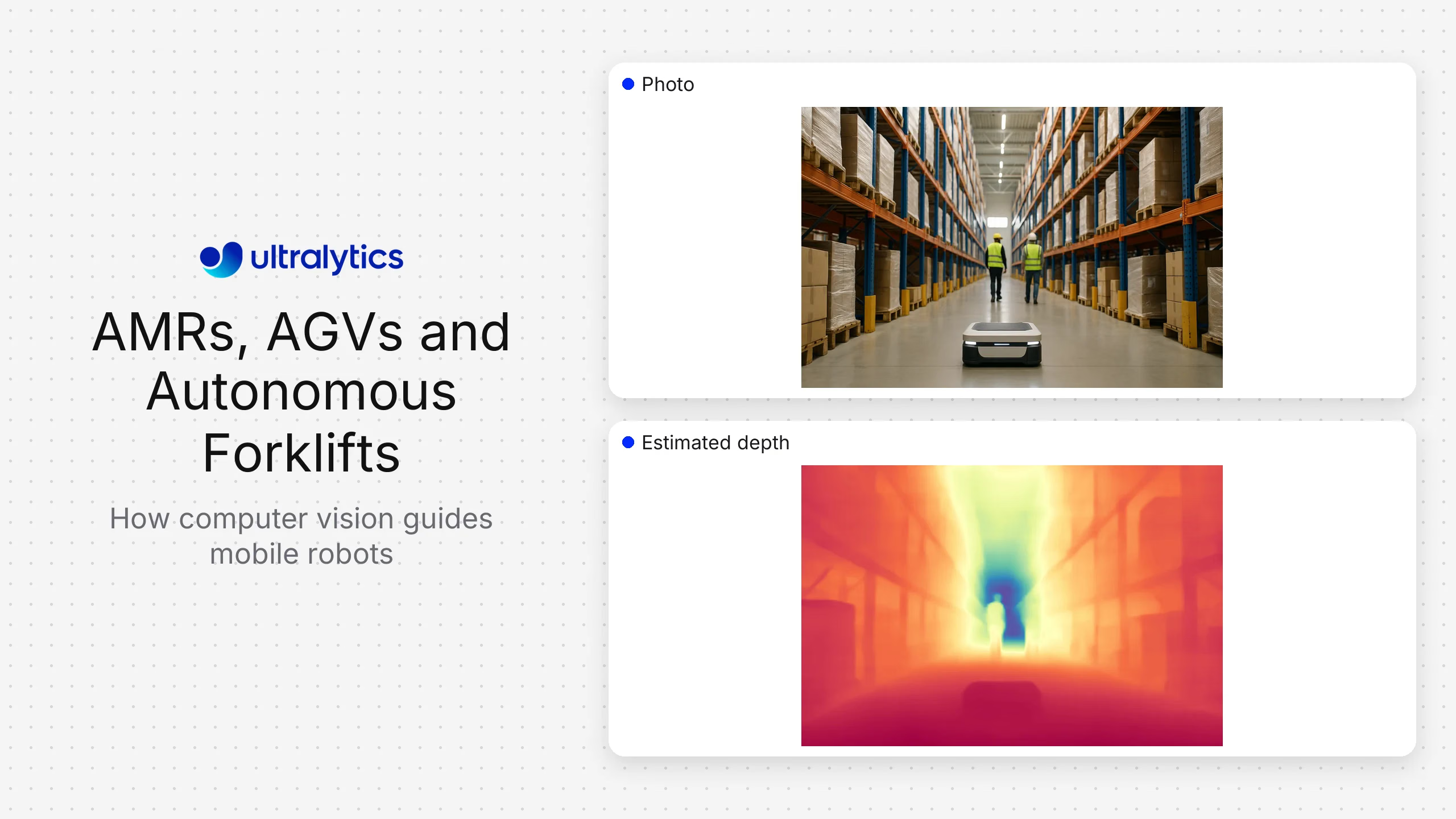
Computer vision helps autonomous mobile robots, automated guided vehicles, and autonomous forklifts perceive people, pallets, racks, loads, signs, floor areas, and other vehicles. Ultralytics YOLO can provide detection, segmentation, pose, and tracking observations within that perception stack. It does not replace localization, route planning, vehicle control, or a validated safety system.
The best architecture is usually sensor fusion. Cameras contribute semantic understanding and rich appearance information. Lidar and depth sensors contribute geometry and range. Encoders and inertial sensors contribute motion. The navigation system combines these inputs according to the vehicle, environment, and risk assessment.
AMR, AGV, and autonomous forklift requirements differ#
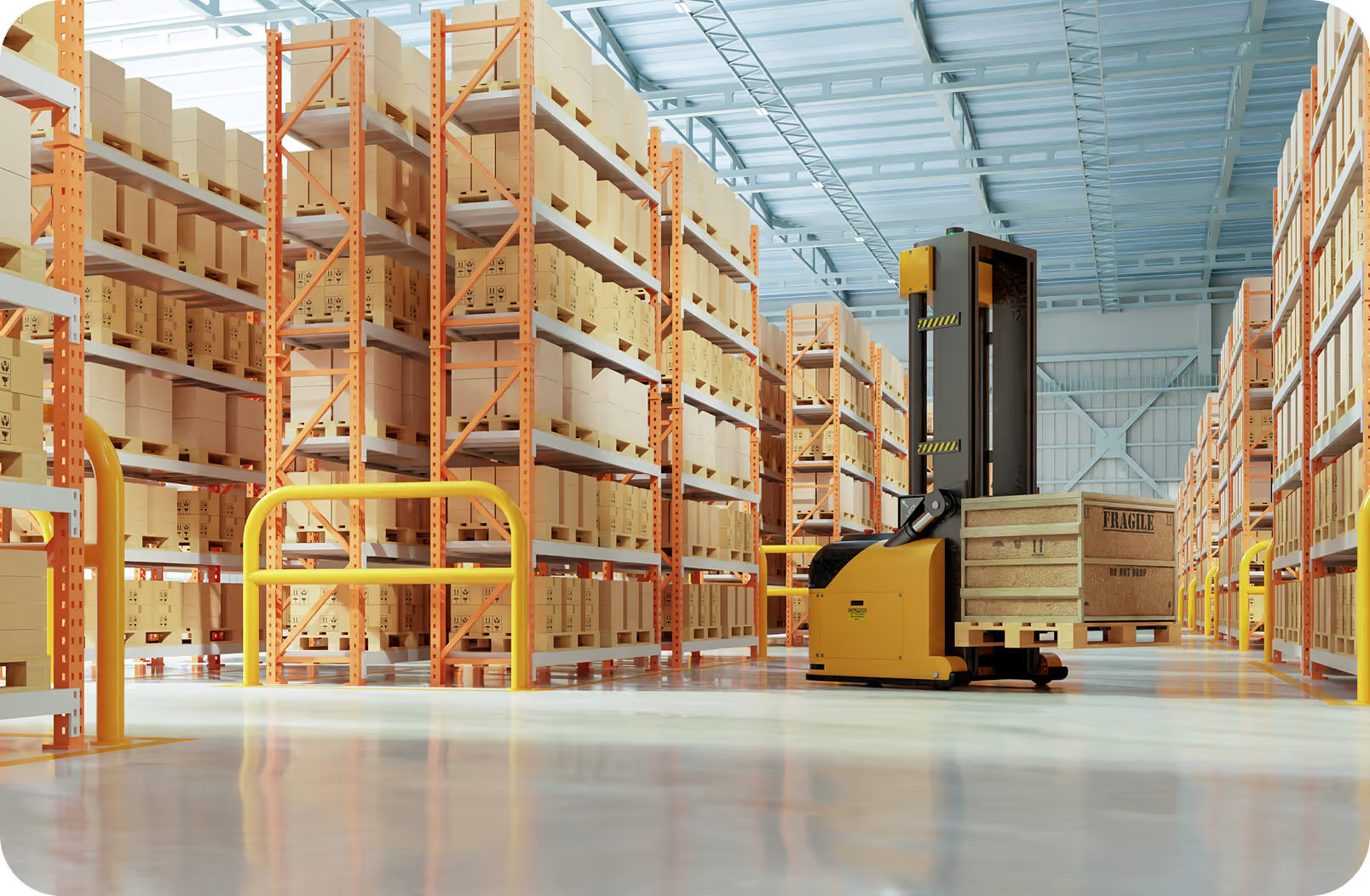
An AGV often follows fixed or semi-fixed routes and depends on infrastructure such as markers, reflectors, or mapped paths. An AMR generally plans around changing obstacles in a mapped environment. An autonomous forklift adds load handling, mast and fork geometry, elevated loads, and interactions around pallets and racks.
Do not use the labels as a substitute for requirements. Define:
- Operating zones and permitted routes.
- Vehicle speed, stopping behavior, and payload range.
- People, vehicles, and object classes that must be perceived.
- Indoor and outdoor lighting, weather, dust, and floor conditions.
- Required localization and map behavior.
- Blind spots created by the vehicle and load.
- Network availability and onboard compute limits.
- Applicable machinery, vehicle, and workplace-safety requirements.
What computer vision contributes#
| Perception function | Possible vision task | Navigation use | Key limitation |
|---|---|---|---|
| Person and vehicle detection | Object detection and tracking | Semantic awareness and behavior logic | Detection is not a safety-rated protective function by default |
| Pallet and rack recognition | Detection, segmentation, or keypoints | Docking, pickup, and placement context | Occlusion and damaged pallets change appearance |
| Free-space estimation | Semantic segmentation or depth | Traversability input | Floor reflections and unseen geometry can mislead a camera-only system |
| Load-state monitoring | Detection or classification | Confirm load presence and visible alignment | Hidden weight and stability need other sensors |
| Sign and marker recognition | Detection plus decoding | Route or workflow context | Dirt, wear, and viewpoint affect readability |
| Visual localization | Feature tracking or visual SLAM | Pose estimation | Repetitive aisles and changing scenes can reduce reliability |
| Object motion | Multi-object tracking | Predict nearby trajectories | Camera motion and occlusion require careful fusion |
The navigation application should consume explicit, time-stamped observations. It needs to know the camera frame, model version, confidence, and age of each result so it can reject stale or inconsistent data.
Camera, lidar, and depth are complementary#
Monocular cameras offer color and texture at relatively low hardware complexity but do not directly measure metric depth. Stereo and active-depth cameras estimate range within their operating envelope. Lidar provides direct geometric measurements and can remain useful where appearance varies, although material, weather, and geometry still matter.
Sensor selection should follow failure analysis. Ask which hazards or navigation features would be missed if one sensor were blocked, saturated, contaminated, or unavailable. Redundancy only helps when failure modes are sufficiently independent and the fusion logic handles disagreement.
Camera placement must account for turning, reversing, fork position, and changing loads. Validate the field of view with the largest permitted load and every mast state. Add cleaning, inspection, and alignment checks to maintenance procedures.
Build the perception dataset from routes, not isolated images#
Collect complete route conditions across sites, shifts, aisle types, intersections, dock areas, people and vehicle traffic, load states, and maintenance conditions. Include hard negatives such as posters, reflections, mannequins, stacked materials, and partial views that resemble target classes.
Split evaluation data by route, time, or site to avoid near-duplicate video frames in training and testing. Report performance by distance, occlusion, lighting, motion, and object type. A single average can hide the cases that matter most near intersections or docking areas.
Ultralytics Platform can support annotation, training, and version management for custom Ultralytics YOLO perception models. Exported models can run on supported onboard or edge runtimes selected for the vehicle's compute and latency constraints.
Integrate perception with ROS 2 or another robotics stack#
A robotics integration typically publishes detections or masks with timestamps and coordinate-frame information. A transform layer relates camera coordinates to the vehicle. The navigation or behavior layer uses the observations alongside maps, range sensors, odometry, and task state.
Design for:
- Time synchronization between sensors.
- Bounded latency and stale-message rejection.
- Camera-health and model-health states.
- Explicit behavior when sensors disagree.
- Recorded data sufficient to reproduce an event.
- Versioned message schemas and model outputs.
- Resource contention between perception, localization, and planning.
Avoid coupling navigation directly to undocumented model output. A stable interface lets perception evolve without silently changing vehicle behavior.
Safety boundary#
General-purpose computer vision can support awareness and operational decisions, but it should not be described as a certified protective device. Vehicle stopping, protective fields, emergency functions, and safety validation belong to the applicable safety architecture and competent engineering process.
Document what happens when the model, camera, compute, or network fails. A safe state may require reduced speed, controlled stop, route restriction, or transfer to another operating mode, depending on the system design. Validate these behaviors on the complete vehicle.
Evaluation plan#
Test perception, navigation, and operations separately and together.
Perception tests#
- Detection and localization by distance, direction, lighting, and occlusion.
- Tracking continuity through crossings and temporary obstruction.
- False positives from background objects and reflections.
- Performance with dirty, shifted, blurred, or partially blocked cameras.
- End-to-end latency and resource use on target compute.
Navigation tests#
- Intersections, narrow aisles, merges, overtaking, reversing, and docking.
- Static and moving obstacles at representative speeds.
- Map changes, temporary barriers, and route closures.
- Sensor disagreement, message delay, and missing input.
- Recovery from localization loss or an unavailable perception component.
Operational tests#
- Load pickup, transport, and placement across pallet variants.
- Behavior with elevated or view-blocking loads.
- Shift changes, charging, startup, shutdown, and maintenance.
- Incident reconstruction and model rollback.
Measure mission completion, interventions, route delays, unavailable time, perception errors, and recovery behavior. Do not infer navigation safety from model accuracy alone.
Deployment choices#
Onboard inference minimizes dependence on network connectivity and can keep high-rate sensor data on the vehicle. It requires controlled software updates, resource monitoring, storage management, and hardware support across the fleet.
Centralized services can simplify model management and aggregate review data, but real-time vehicle behavior should account for network latency and loss. A hybrid design can run immediate perception onboard while centrally managing approved model artifacts, metadata, and selected review examples.
Use staged releases. Start with recorded replay, then a test area, shadow observations, restricted operations, and a controlled fleet subset before broad rollout. Preserve a known-good model and configuration for rollback.
Frequently asked questions
Visual simultaneous localization and mapping estimates camera motion while building or using a map from visual features. It is one localization approach and may be combined with inertial, wheel, lidar, or other measurements.
Onboard inference is appropriate when low latency, data locality, or operation during network loss matters. Confirm that the target compute can sustain the complete workload and that fleet updates and monitoring are supportable.
Detect missing, stale, blurred, blocked, shifted, or implausible input and route that state into defined vehicle behavior. The response must be designed and validated as part of the complete system.